Overview:
Wing skin panes are part of the various components of the wing
structure like flaps, aerolons and spar caps. The basic functionality of the
wing skin that it provides a smooth contoured surface which provides lifting
for the aircraft. From its basic name “wing skin” this part is regarded as an
outer layer thin sheet for the wing structure in which its bending deformation
provides the aerofoil shape of the whole wing. Wing types, theory and
loading will be discussed in details.
Wing
types
Aircraft can be
categorized by their configurations. One measure is the number of wings, and
the styles include monoplanes, with a single wing (that is, on either side of the
fuselage); biplanes, with two wings, one atop the other; and even, though
rarely, triplanes and quadplanes. A tandem-wing craft has two wings, one placed forward of the other.
The wing planform is the shape it forms when
seen from above. Delta wings are formed in the shape of the Greek letter delta (D)
and are triangular wings lying at roughly a right angle to the fuselage. The
supersonic Concorde features delta wings.
Swept wings are
angled, usually to the rear and often at an angle of about 35°. Forward swept
wings also are used on some research craft.
Some aircraft have wings that may be adjusted
in flight to attach at various angles to the fuselage; these are called variable incidence wings. Variable geometry (swing) wings can vary the sweep (i.e.,
the angle of a wing with respect to the plane perpendicular to the longitudinal
axis of the craft) of their wings in flight. These two types have primarily
military applications, as does the oblique wing, in which the wing is attached at an angle of about 60°
as an alternative to the standard symmetrical wing sweep.
 Another configuration limited to
military craft is the so-called flying wing, a tailless craft having all its elements encompassed
within the wing structure (as in the Northrop B-2 bomber). Unlike the flying
wing, the lifting-body aircraft (such as the U.S. space shuttle) generates lift
in part or totally by the shape of the fuselage rather than the wing, which is
severely reduced in size or altogether absent.
Another configuration limited to
military craft is the so-called flying wing, a tailless craft having all its elements encompassed
within the wing structure (as in the Northrop B-2 bomber). Unlike the flying
wing, the lifting-body aircraft (such as the U.S. space shuttle) generates lift
in part or totally by the shape of the fuselage rather than the wing, which is
severely reduced in size or altogether absent.
 Wing theory:
The type of operation for which an airplane
is intended has a very important bearing on the selection of the shape and
design of the wing for that airplane. If the airplane is designed for low
speed, a thick airfoil is most efficient. A thin airfoil is best for high
speed.
CONVENTIONAL AIRFOILS and LAMINAR FLOW
AIRFOILS , are in common use in
airplane design.
Laminar flow airfoils were originally
developed for the purpose of making an airplane fly faster. The laminar flow
wing is usually thinner than the conventional airfoil, the leading edge is more
pointed and its upper and lower surfaces are nearly symmetrical. The major and
most important difference between the two types of airfoil is this, the thickest
part of a laminar wing occurs at 50% chord while in the conventional design the
thickest part is at 25% chord.
The effect achieved by this type of design of
a wing is to maintain the laminar flow of air throughout a greater percentage
of the chord of the wing and to control the transition point. Drag is therefore
considerably reduced since the laminar airfoil takes less energy to slide
through the air. The pressure distribution on the laminar flow wing is much
more even since the camber of the wing from the leading edge to the point of
maximum camber is more gradual than on the conventional airfoil. However, at
the point of stall, the transition point moves more rapidly forward.
The type of operation for which an airplane
is intended has a very important bearing on the selection of the shape and
design of the wing for that airplane. Boundary layer effects play a very
important part in determining the drag for the aircraft. Thus, the wing
should be designed to minimize the drag.
THE BOUNDARY LAYER
The boundary layer is a very thin layer of
air lying over the surface of the wing (and, for that matter, all other surfaces
of the airplane). Because air has viscosity, this layer of air tends to adhere
to the wing. As the wing moves forward through the air, the boundary layer at
first flows smoothly over the streamlined shape of the airfoil. Here the flow
is called the laminar layer.
As the boundary layer approaches the center
of the wing, it begins to lose speed due to skin friction and it becomes
thicker and turbulent. Here it is called the turbulent layer. The point
at which the boundary layer changes from laminar to turbulent is called the
transition point (Fig. 3). Where the boundary layer becomes turbulent, drag due
to skin friction is relatively high. As speed increases, the transition point
tends to move forward. As the angle of attack increases, the transition point
also tends to move forward.
Fig. 3
Various methods have been developed to
control the boundary layer in order to reduce skin friction drag.
Suction Method. One method uses a series of thin slots in the wing
running out from the wing root towards the tip. A vacuum sucks the air down
through the slots, preventing the airflow from breaking away from the wing and
forcing it to follow the curvature of the wing surface. The air, which is
sucked in, siphons through the ducts inside the wing and is exhausted backwards
to provide a little extra thrust. The laminar flow airfoil is itself a
structural design intended to make possible better boundary layer control. The
thickest part of a laminar flow wing occurs at 50% chord. The transition point
at which the laminar flow of air breaks down into turbulence is at or near the
thickest part. The transition point at which the laminar flow of air becomes
turbulent on a laminar flow airfoil is rearward of that same point on a
conventional designed airfoil.
Vortex generators are small plates about an inch deep standing on edge
in a row spanwise along the wing. They are placed at an angle of attack and
(like a wing airfoil section) generate vortices. These tend to prevent or delay
the breakaway of the boundary layer by re-energizing it. They are lighter and
simpler than the suction boundary layer control system described above.
Airfoils and the production of lift:
Air weighs about .0078lbs/cu. ft. This means
that many cubic feet of air must pass over the wing to create sufficient lift
to carry the all up weight (AUW) of the aircraft. Conventional thick airfoils
have a thickness ratio to the wing chord of 15% to 18%. This thick airfoil
creates a high lift, slow flying wing. It is suitable for a low horsepower,
land based aircraft. This type of airfoil is also used with amphibious aircraft
that need a lot of horsepower and lift to break free from the water.
Medium thick airfoils are about 12% thickness
ratio to the wing chord. These airfoils do not create as much lift at slow
speeds and need to move faster through the air to carry a similar load as the
thicker airfoil sections. The 12% airfoil also stalls at higher speeds than the
thicker airfoil. Aircraft with a 12% airfoil fly faster and often use more
horsepower when used in aerobatic type aircraft. This type of airfoil section
is mainly used on conventional land based sport aircraft.
A low profile airfoil section of 8% thickness
ratio to wing chord is called a Laminar Flow Airfoil and is used for
high-performance, high speed, and some touring aircraft. Laminar flow airfoil
sections have a high stall speed and require a perfect smooth leading edge to
produce the lift required to make the aircraft fly.
Any contamination on the leading edge of the
wing by bugs, irregularities, or indentations by airborne particles will
destroy the lift capabilities of the airfoil. Under these circumstances, it is
guaranteed that the wing will become ineffective and the aircraft will stall.
Aircraft with this type of airfoil are not
recommended for low time and recreational pilots. However, some modern
designers are trying to address this problem. They are designing
user-friendlier laminar flow airfoils. An example would be the Europa Aircraft
Company in Britain.
Thick airfoil sections have strong deep spars
that allow for long wing panels. Example: The Coot Amphibian has a 15%
thickness to chord and a wingspan of 36 ft. Thin airfoil sections do not have
deep spars. They tend to have short wing panels due to structural problems with
long, thin spars. Example: The Cassutt Racer with a wingspan of 15 ft.
Wing load:
This is the ratio of all up weight to wing
area. (AUW to WA.) For conventional aircraft, the calculations are as follows.
With less than 6lbs per square foot the aircraft tends to float down the runway
when landing. This means that the wing generates a lot of lift and counteracts
the gravitational pull of the AUW of the aircraft. This type of aircraft
usually has a big wing area in relationship to the AUW. This light aircraft
design is said to be "light." A light aircraft design with a wing
load over 15lbs per square foot is said to be "heavy."
Heavy aircraft will stall sooner and do not
float down the runway on landing. Example: A Boeing 747 fully loaded to its
design limits may weigh 380 tons at take off. After burning up 150 tons of fuel
on its journey, the aircraft may only weigh 230 tons and its wing load is so
light, it will float down the runway like a glider.
Single seat light aircraft designs are about
8lbs to 10lbs per square foot. Two seat light aircraft designs are somewhere
between 12lbs to 15lbs per square foot. A 2-seat amphibian should have a wing
load of about 10lbs to 12lbs/sq. ft. The stall speed of an aircraft is the
minimum flight, or crash speed. Aircraft stall speed is directly related to the
aircraft wing load. Low wing load = low stall speed. High wing load = high
stall speed. An aircraft with no flaps and a low wing load of about 8lbs/sq.
ft. stalls at about 48mph. An aircraft with a high wing load of about 15lbs/sq.
ft. will stall well over 70mph. The landing speed may be reduced by about 5mph
due to ground effect.
Composites are ideal for applications where
high stiffness and low weight are required. A classic example of such a product
is an airplane wing. In this week's feature, we'll take a detailed look at a
typical composite wing design.
Terminology
|
|
|
Typical Wing Section |

The curved edge on
the left is called the leading edge; it is the forward edge of the wing.
The pointed edge on the right is called the trailing edge. The distance
from the leading edge to the trailing edge is called the chord. This
sample has a chord length of 18 inches. A full wing may have a constant or a
varying chord.
The two vertical
members are the spars. The one closest to the leading edge is the forward
spar; the one closest to the trailing edge is the aft spar. The
forward spar is actually an I-beam--the vertical piece is the spar web
and the thick graphite plates at top and bottom are the spar caps. The
spar carries most of the bending load in the wing.
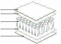
Wing Design
The wing is made in several parts. The upper
and lower skins are layed up separately in female tools (the outer sides are
placed against the tool face). Nomex honeycomb is used to increase the bending
stiffness of the skins.
|
|
|
Forward Spar |

The spars are layed up on a flat table; the
web and caps of the forward spar are layed up separately. Both webs have a
Nomex honeycomb core, but a real wing might have local reinforcements of solid
graphite or some other material for point loadings.
To assemble the wing, the spar caps are
bonded to the upper and lower skins. The high loads carried through the spar
could cause the honeycomb to fail, so the skin core must be tapered at the
spars. This wing uses a 30 degree taper, which is typical for most structures.
Larger angles would create a high stress concentration at the taper; smaller
angles would be difficult to manufacture.
Next, the webs are then bonded to the lower
skin or spar cap (it could just as easily be the upper). A relatively thick
layer of adhesive goes between the web and skin, and then one or two plies of
graphite are layed up over both the web and skin to provide better load
transfer. These latter plies form an "L" shape, and are sometimes
called angle plies.
|
|
|
Leading Edge |

Once the spars are in place, the upper skin
can be bonded in place. The spar bonds on the upper skin are similar to the
lower skin (the actual process is rather tricky, because you don't have access
to the inside on a full wing).
The leading edge bond is a simple lap joint.
The honeycomb on both the upper and lower skins tapers at the leading edge--the
curvature of the wing provides enough stiffness here. The upper skin curves
around well onto the lower skin (the red line of adhesive shows the end of the
upper skin). The lower skin curves roughly halfway up the sharp bend of the
leading edge. Because the lower skin goes on the outside, the upper skin must
have a slight step (equal to the thickness of the lower skin) to keep the
leading edge smooth.
|
|
|
Trailing Edge |

The trailing edge bond looks simpler, but it
is actually more difficult. Because it comes to a point, the skins can't wrap
around each other. Instead, a thick adhesive paste layer is placed on the lower
skin and the upper skin is pressed into this layer. Ideally, the honeycomb
would be continued all the way to the edge, but it must be tapered earlier to
fit the skins together.
The wing is finished by priming and painting.
In this case, standard automotive paint is used. Some paint has been left off
the trailing edge to show the original surface. The thin gray band is the
primer coat.
This sample is typical of a composite wing,
but it is not identical to any existing wing designs. In particular, the forward
spar caps are much thicker than they need to be for a wing this size. Also,
this wing section lacks any control surfaces such as ailerons.
Core
Materials for Sandwich Structures
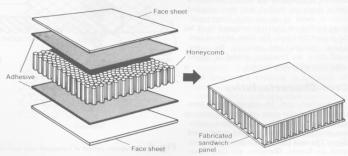
Bonded sandwich
structures have been a basic component of the composites industry
for over 45 years. The concept of using relatively thin, strong face sheets
bonded to thicker, lightweight core materials has allowed the industry to build
strong, stiff, light and highly durable structures that otherwise would not be
practical. This technology has been demonstrated in boats, trucks, and building
panels. A 3% weight increase can increase the flexural strength and stiffness
by a magnitude of 3.5 times and 7 times respectively if cores and skins are
properly chosen. The structure then acts more or less monolithically.
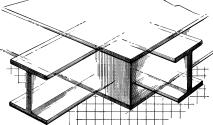
The most common comparison made is that of a composite sandwich to an
I-beam. The panel skins, like the flanges of the I-beam, carry the stresses imposed
by use. The stresses are transferred between the top and bottom skins through
shear stresses that run through the core or web of the I-beam. The purpose of
an I-beam is to lessen the weight required to support a given load in bending.
Since the highest stresses are carried at the extremities, both the top and
bottom of the I-beam, the center section can be much narrower in width in
relation to the flanges. In a sandwich structure, the core will generally have
the same width and length dimensions as the skins, but can be much weaker than
the skins since it primarily experiences shear stresses. Care must be taken in
design to ensure that the shear carrying capability of the expected loads does
not exceed both the core and the adhesive.
Face sheets can be
of almost any material. In the composites industry, the most common face sheets
are glass and carbon. The common core materials are foam, syntactic foam, honeycomb, and balsa wood. Some core materials can be shaped, such as a
waffle pattern or corrugation to achieve the desired mechanical properties.
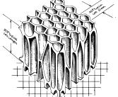
 Honeycomb
Sandwich Construction
Honeycomb
Sandwich Construction
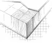
A cost-effective and superior sandwich construction uses end-grain balsa
wood. This material has exceptional bond, high impact and fatigue resistance
with excellent strength/stiffness and lightweight properties. Balsa wood is
“mother nature’s” honeycomb material. Balsa has a high-aspect ratio and
directionally aligned cells such that the grain is oriented in the direction of
the maximum stress. Balsa has a proven track record in products such as
pleasure boat hulls, military aircraft, vehicles, and corrosion-resistant
industrial tanks.
 Laminated
Sandwich Construction with Balsa Wood
Laminated
Sandwich Construction with Balsa Wood
The
first composite material to be used widely for ground transportation was
honeycomb, a lightweight structurally stiffening material. Today, honeycomb can
be metallic (Aluminum) or non-metallic (Aramid, Glass, Paper), and when
sandwiched between facing skins it forms an exceptionally lightweight but stiff
construction.
It is easy to see why honeycomb was quickly adopted for ground transportation.
It requires no special equipment or handling, and can be cut and shaped using
simple woodworking tools. It is also considered as a non-combustible material,
meeting today’s fire, smoke and toxicity (FST) regulations.
Aluminum honeycomb possesses remarkable kinetic energy absorbing properties.
The honeycomb crushes under load in a uniform way, preventing damage to the
supporting structure. Being virtually free of rebound and lighter than
alternative materials, aluminum honeycomb is one of the most reliable efficient
and practical energy absorbing materials available.In the rail industry,
aluminum honeycomb is the ideal materials for buffers, fenders and driver
protection. Hexcel supplies energy absorbers to the JT42 (Alstom, Spain), Loco
2000 (SLM and BLS, Switzerland), Pendolino (Alstom Spain and Fiat Ferroviaria,
Italy), TGV Korea (Alstom, France) and BB36000 (Alstom, France) projects.
Wing construction and loading:
The particular wing design depends upon many
factors for example, size, weight, use of the aircraft, desired landing speed,
and desired rate of climb. In some aircraft, the larger compartments of the
wings are used as fuel tanks. The wings are designated as right and left,
corresponding to the right- and left-hand sides of a pilot seated in the
aircraft.
The wing structures of most naval aircraft
are of an all-metal construction, usually of the cantilever design; that is, no
external bracing is required. Usually wings are of the stress-skin type. This
means that the skin is part of the basic wing structure and carries part of the
loads and stresses. The internal structure is made of "spars and
stringers" running spanwise, and "ribs and formers" running
coordwise (leading edge to trailing edge). The spars are the main structural
members of the wing, and are often referred to as "beams."
One method of wing construction is shown in
figure 1-5. In this illustration, two main spars are used with ribs placed at
frequent intervals between the spars to develop the wing contour. This is
called "two-spar" construction. Other variations of wing construction
include "monospar (open spar), multispar (three or more spars), and box
beam." In the box beam construction, the stringers and sparlike sections
are joined together in a box-shaped beam. Then the remainder of the wing is constructed
around the box.
The skin is attached to all the structural
members and carries part of the wing loads and stresses. During flight, the
loads imposed on the wing structure act primarily on the skin. From the skin,
the loads are transmitted to the ribs and then to the spars. The spars support
all distributed loads as well concentrated weights, such as a fuselage, landing
gear, and nacelle. Corrugated sheet aluminum alloy is often used as a
subcovering for wing structures. The Lockheed P-3 Orion wing is an example of
this type of construction. Inspection and access panels are usually provided on
the lower surface of a wing. Drain holes are also placed in the lower surfaces.
Walkways are provided on the areas of the wing where personnel should walk or step.
The substructure is stiffened or reinforced in the vicinity of the walkways to
take such loads. Walkways are usually covered with a nonskid surface. Some
aircraft have no built-in walkways. In these cases removable mats or covers are
used to protect the wing surface. On some aircraft, jacking points are provided
on the underside of each wing. The jacking points may also be used as tiedown
fittings for securing the aircraft.
Why sandwitch structure?
The stiffness of a material is dependent upon
its thickness, by making the material thicker, its stiffness is increased. For
example a thick, light beam is needed for load bearing in an aircraft.
Consequently, many composite materials are designed with a thick, light core
sandwiched between two fibre reinforced or prepreg fabric panels.
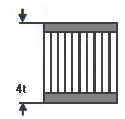
The table below shows how this design works.
|
|
Solid Laminate |
Sandwich Panel |
Thicker Sandwich |
|
|
|
|
|
|
Stiffness |
1.0 |
7.0 |
37.0 |
|
Flexural Strength |
1.0 |
3.5 |
9.25 |
|
Weight |
1.0 |
1.03 |
1.06 |
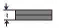
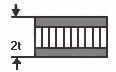
By doubling the thickness, the stiffness
increases by x7.
However, in order to maintain the strength of the material, the core must be
able to withstand large forces. This problem is usually overcome by using core structures,
the composite is made up as shown:
|
Pepreg skin |
|
The type of
operation for which an airplane is intended has a very important bearing on the
selection of the shape and design of the wing for that airplane. Planform
determines the stall characteristics of the wing. Angle
of incidence of the wing improves flight visibility, enhances take-off
and landing characteristics and reduces drag in level flight. Wing
washout helps to control the aircraft near its stall angle, the angle
at which the lift coefficient of the wing drops drastically.
PLANFORM
Planform refers to the shape of the wing as seen from directly
above. Wings may be rectangular or elliptical or delta shaped. Some wings taper
from wing root to wing tip, with the taper along the leading edge or along the
trailing edge or, in some cases, with a taper along both edges.
The aspect ratio of a wing is the
relationship between the length or span of the wing and its width or chord. It
is computed by dividing the span by the average chord.
A wing, for example, that has a span of 24
feet and a chord of 6 feet has an aspect ratio of 4. A wing with a span of 36
feet and a chord of 4 feet has an aspect ratio of 9. The actual size, in area,
of both wings is identical (144 sq. ft.) but their flight performance is quite
different because of their differing aspect ratios.
A wing with a high aspect ratio will generate
more lift and less induced drag than a wing with a low aspect ratio.
For this reason, gliders have wings with high
aspect ratios.
ANGLE OF INCIDENCE
The angle of incidence is the angle at
which the wing is permanently inclined to the airplane’s longitudinal axis.
 Choosing the right angle of incidence can improve
flight visibility, enhance take-off and landing characteristics and reduce drag
in level flight.
Choosing the right angle of incidence can improve
flight visibility, enhance take-off and landing characteristics and reduce drag
in level flight.
The angle of incidence that is usually chosen
is the angle of attack at which the lift-drag ratio is optimum. In most modern
airplanes, there is a small positive angle of incidence so that the wing has a
slight angle of attack when the airplane is in level cruising flight.
WASHOUT
To reduce the tendency of the wing to stall
suddenly as the stalling angle is approached, designers incorporate in wing
design a feature known as washout. The wing is twisted so that the angle
of incidence at the wing tip is less than that at the root of the wing. As a
result, the wing has better stall characteristics, in that the section towards
the root will stall before the outer section of the wing. The ailerons, located
towards the wing tips, are still effective even though part of the wing has
stalled.
The same improved stall characteristics are
achieved by the device of changing the airfoil shape from the root to the tip.
The manufacturer incorporates a wing shape at the tip, which has the
characteristic of stalling at a slightly higher angle of attack.
Wing construction is basically the same
in all types of aircraft. Most modern aircraft have all metal wings, but many
older aircraft had wood and fabric wings. Ailerons and flaps will be studied
later in this chapter.
To maintain its all-important
aerodynamic shape, a wing must be designed and built to hold its shape even
under extreme stress. Basically, the wing is a framework composed chiefly of
spars, ribs, and (possibly) stringers (see figure 1-5). Spars are the main
members of the wing. They extend lengthwise of the wing (crosswise of the
fuselage). All the load carried by the wing is ultimately taken by the spars.
In flight, the force of the air acts against the skin. From the skin, this
force is transmitted to the ribs and then to the spars.
Most wing structures have two spars, the
front spar and the rear spar. The front spar is found near the leading edge
while the rear spar is about two-thirds the distance to the trailing edge.
Depending on the design of the flight loads, some of the all-metal wings have
as many as five spars. In addition to the main spars, there is a short structural
member which is called an aileron spar.
The ribs are the parts of a wing which
support the covering and provide the airfoil shape. These ribs are called
forming ribs. and their primary purpose is to provide shape. Some may have an
additional purpose of bearing flight stress, and these are called compression
ribs.
The most simple wing structures will be found
on light civilian aircraft. High-stress types of military aircraft will have
the most complex and strongest wing structure.
Three systems are used to determine how wings
are attached to the aircraft fuselage depending on the strength of a wing's
internal structure. The strongest wing structure is the full cantilever which
is attached directly to the fuselage and does not have any type of external,
stress-bearing structures. The semicantilever usually has one, or perhaps two,
supporting wires or struts attached to each wing and the fuselage. The
externally braced wing is typical of the biplane (two wings placed one above
the other) with its struts and flying and landing wires (see figure 1-6).
Wing
Structure subjected loads
|
||||
|
Aircraft Wings are usually subject to two
different types of load:
The wing structure need to be designed to
carry these types of loads Bending
The amount of bending load at any point on
a beam is called the bending moment. Bending
Moment = Force x Distance The bending moment varies along the beam.
The further away from the load a section of
beam is, the stronger it needs to be. In reality, the wing lifting load
distribution is as follows:
So the bending moment distribution looks
like:
The upwards force is trying to push the
beam up. If it isn’t to move, the supporting structure must be supplying a
downwards reaction force.
The upwards force and downwards reaction
will try to make the beam rotate. There must be some other reaction forces
trying to stop the beam rotating. The support exerts a number of small forces
along the beam to prevent rotation.
These forces make the bottom of the beam
increase in length, and the top of the beam decrease in length. This causes
the beam to form a curved shape (a bend).
The part of the beam which does not change
length is called the Neutral Axis. These tension and compression loads are
highest, furthest away from the neutral axis. When designing a structural
beam cross-section we need to keep the material as far as possible away from
the neutral axis, where it will carry no load, and hence be wasted. The
deeper the beam, the greater the bending strength.
Shear
We now have a way of carrying the loads
along the wing. But we still have to carry the up and down loads (known as shear
loads). The shear loads are trying to make the wing adopt a lozenge
shape.
The shear loads are best resisted by carbon
fibres at +/- 45 degrees to the vertical loads, effectively cross bracing the
panel. We can now put all of these elements into a
single structural member. In a wing, this type of beam structure is known as
a spar. A cross-section through a typical spar is shown below.
The F1 wing has two spars to carry the
bending loads.
Torsion
If the bending force applied to an I-beam
does not pass through the center of the beam cross section, the beam will
twist, at the same time as bending.
The point through which a force can be
applied without twist occurring is called the Torsional Centre. For
symmetric beam sections, it is at the centre of the section. For other
sections, it can be some way away from the centre.
The best cross sections to carry torsion
loads have their material as far away as possible from the torsional axis.
The best possible distribution is a circle.
The loads at the centre of a torsional
member are low, so we can save weight by removing the material at the centre,
which isn’t working very hard, and make the cross section hollow.
In conjunction with our wing skins, the
spar webs form three closed sections that we can use to carry our torsional
loads.
The spar webs already have +/- 45 degree
fibres to carry shear loads. We simply have to make the wing skins contain
+/- 45 degree fibres as well.
In the area of the undercarriage, we have a
cut in the lower wing skin. This destroys the torsion carrying capabilities
of one of our cells. We have replaced the single web spars with double web
box spars to get back some of this torsional capability. Wing Skin Buckling
As the tops of our spars stretch and
compress, the wing skins glued to them will have to stretch.
The upper wing skins are in compression in
normal flight and we have to make sure that they don’t buckle. (The lower
skins are in compression in negative ‘g’ manoeuvres.) We can do this in two
ways:
1. Shorten the unsupported length of wing
skin
This is done by breaking the wing into
shorter sections using ribs. These also have the function of maintaining the
wing aerofoil shape in response to the wind loads on it.
2. Increase the bending stiffness of the
skin
This is done by attaching small beams to
the wing skins. These are called stringers. box section beams is
used to add a small amount of torsional resistance to the skins as well.
We can now put the whole wing structure together.
In practice the functions of each of the
components overlap slightly. For example, the wing skins will have some
spanwise carbon in them as well as +/-45, to carry some bending loads, but
the pure split functions described above make it easier to do initial design
work and strength calculations. |
Refrences:
http://composite.about.com/industry/composite/cs/applications/index.htm
http://www.allstar.fiu.edu/aero.html
http://www.aerospaceweb.org/design/ucav/design.shtml
http://www.farnboroughaircraft.com/Aircraft_Design_Theory/Wing_Structure/Wing_Structure.asp